Tuesday, November 29, 2011

Multi-Part Fixture

The Techmor IM-1 Inertial Measurement Unit is one of many high-precision measurement instruments and controls developed by Techmor Inc.

DMD was fortunate to participate in the manufacture of these instruments in quantity. In order to make them cost effective for the quantity needed, DMD used a multi-part fixture arrangement that incorporated Mitee Bite Pitbull Clamps. The fixture is designed so that the parts can be held in six different positions so that all of the operations to machine the parts can be done on one fixture.


The Haas TM-1 has a 4000 RPM spindle. In order to cut the smaller details in the aluminum pieces and also to cut the carbon fiber lids, DMD uses a High Speed Spindle Adapter to bump up the revs.


Saturday, November 26, 2011

Brake Rotor Adapter for Norton Motorcycle

I have a really good customer, Rick at Lance Gamma who needs custom motorcycle parts all the time. This time his project is an old Norton 850 Commando.

1975 Norton 850 Commando Electric

The previous owner installed a wider rear rim and spoke set which resulted in the wheel being not centered properly.

Poorly centered rear wheel

Rick's has access to more shop services ( like DMD ), so he envisioned a fix for the problem that required some customizing of the factory brake rotor.

Original integrated brake rotor and adapter

Removing the center wheel interface from the rotor

His idea involved designing and manufacturing a custom brake rotor hub with the proper offset. The factory rotor is a one-piece cast iron unit with an integrated rotor and wheel mount interface. The first step in the project was to remove the existing wheel interface. The above pic shows the rotor center being milled out. Below is the rotor with the center milled away.

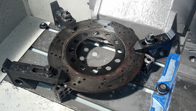
Center milled out of rotor

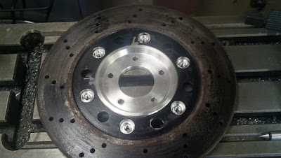
The center was milled out to a diameter of 4.500in which allowed for the entire center to clean up nicely. The design of the new system calls for the large diameter hole pattern in the center web to be used as driving features for the rotor. While the rotor was positioned, the centers of the holes were located to get the hole pattern information. Unfortunately, it was found out that the holes were only generally located in a circular pattern. It was decided that they should be opened up and centered in a properly spaced pattern.

6 holes opened up in rotor

The new assembly was then drawn up in SolidWorks. From the outside, the shape of the new assembly resembles the shape of the original cast piece.

Rotor Assembly

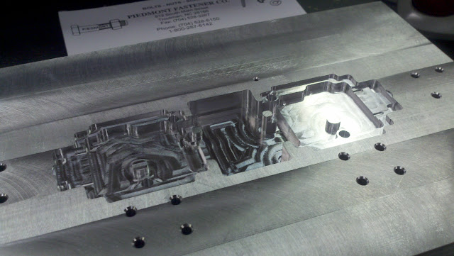
The new design is a simple one with very straightforward features. Since this is not a piece going on a $150k vehicle, it was necessary to keep manufacturing costs low.

New center hub

Since I was all out of 7in diameter round stock, the part had to be machined from a piece of plate. Two dowel pin holes were added to the bolt circle and were drilled and reamed into the plate along with the 5 fastener holes.

Plate with locating pin holes and bolt holes

Matching dowel holes and threaded fastening holes were drilled into a fixture plate and the stock for the new hub was bolted down. The outer profile and all critical locating features were then milled into the part.

Machining the rotor adapter shape and features

Hub milling complete

The hub face around the five mounting bolts was recessed on the lathe.

Recessed hub face with rotor installed

Buttons were made to provide a "driving" interface for the rotor to the hub rather than a clamping load or driving off the threads of the bolts. Thermal stress was discussed, but was ruled out as an issue based on the sizes of the components and the fact that the rotor is mounted on the rear of what is not a high performance bike. In the end, there is a small amount of radial take-up in the tolerances of the pieces to accommodate the differences between the two pieces.

Rotor mounting buttons and stainless screws installed

The bike is designed such that a stub shaft holds the brake hub in place while the axle and wheel are removed. For the offset design, a new, longer shaft needed to be made. The replacement was made from stainless steel.

Turning the shaft on the lathe

Adding the flats

Rick collected the parts and reassembled the bike back at his shop.

Wheel after relocation (There's an RG500 next to it in the pic)

As you can see, the wheel is much better centered. Rick says that he thinks he could have gone a bit farther, but the fit is good and keeps the chain lined up correctly.

Chain side view

The new hub fits very nicely with the original scheme

This pic shows the new hub and drive buttons

Friday, November 11, 2011

Custom Electronics Fixturing

I have a good customer in OSCIUM. They specialize in test equipment that utilizes the iPad, iPhone, and iPod touch interfaces.


This past year I made a number of fixtures for their programming interface for their PCB's. They asked that I not share any pictures of the programming fixtures, but here is a picture of one of the soldering fixtures that I manufactured for them.


They have recently been displaying their products at trade shows. I was asked to make some display fixtures for them out of acrylic material. I was very pleased at how well the acrylic machined. I had no experience with this material but was able to do some searching on some of the forums and found some useful suggestions that I could use; the most important being "use SHARP cutting tools".


Based on my success with the acrylic on this project, I have been thinking of some ideas of my own using this beautiful material. I hope to get some design work done and some pieces made soon.